Werner Almesberger
2011-04-27 22:21:59 UTC
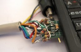
The original ubb-vga used fancy semiconductors (diodes) to generate the
0.7 V analog color signals. I've now made a simpler version with only
resistors:
Loading Image...
This looks a bit more chaotic that it really has to be, because I've
also been experimenting with some other signals and there are still
some remains of those experiments in evidence, e.g., the 1 kOhm
resistor pointing straight up.
David Kuehling has suggested the use of the Ben's MMC controller to
generate the pixel data. One problem with MMC/SD/SDIO is that these
protocols require handshakes with the device. For example, a block
write looks like this:
1. host sends the command on CMD
2. device sends a reponse on CMD
3. host sends the block on DAT0-DAT3
4. device sends a handshake on DAT0
5. if sending multiple blocks, repeat steps 3 and 4
For further details, see
http://www.jedec.org/sites/default/files/docs/JESD84-A441.pdf
(requires registration but doesn't need a valid e-mail address)
The response has a start bit (0) followed by some data, and then a
stop bit (1). The handshake is pulling DAT0 low while busy.
Since we don't have a real MMC/SD/SDIO device, we need to fake these
responses. I'll leave faking the DAT0 handshake for later. In any
case, we need to fake the command response, or the transfer will
never start.
I found a simple way to do this: add a 330 Ohm pull-down to CMD, use
CMD for HSync, and switch CMD briefly from GPIO to the MMC controller
so that it can see the "response". Luckily, it doesn't try to
interpret the response code.
By aligning the response's start bit with (active-low) HSync pulse,
the whole kludgery is transparent to the VGA monitor.
Here is a first impression of what this looks like:
Loading Image...
The timing is more accurately VGA than what I had before. Note that
the whole display content now fits on the screen and all pixels
have the same width.
The timing also happens to be a bit more fragile in the sense that
the monitor sometimes gets very confused. Not sure yet what causes
this.
- Werner